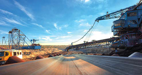
Conveyor drive technology specialist, Flender, is teaming mechanics with digitalization to create the next chapter
in mechanical drive solutions. (Photo: Flender)
Ready to Handle Anything
We present new insights, equipment and installations in mine materials handling
By Carly Leonida, European Editor
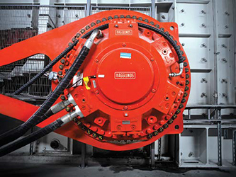
Hägglunds Drives Power
Aitik
Hägglunds, a brand of Bosch Rexroth,
has installed hydraulic direct drives at
a new crushing plant for Bolidens Aitik
copper mine in Sweden. The company
detailed this in a recent case study.
Aitik has a long-term goal to raise its production from 36 to 45 million tons of crushed ore. To achieve this and improve the consistency and reliability of production, Boliden has invested in a new crushing plant with two spindle crushers. The feed system for the plant was designed by Metso in the US, and adapted to suit Aitiks needs in collaboration with Hägglunds, which supplied four CBm hydraulic Hägglunds motors. One reason why Boliden decided to invest in apron feeders with direct hydraulic drives was frequent problems with gearboxes. The operator also set high demands for the performance of the equipment. Metso drew up a specification of requirements based on two motors that share the load on each feed unit, with a capacity of 8,000 metric tons per hour (mt/h), a variable speed of 07.46 rpm and a starting torque of around 1,000,000 Nm.
The drive systems take up minimal space and allow fast replacement of components, thanks to the splined couplings. The main benefits are that we have improved availability while reducing maintenance costs, said Larsson. The hydraulic drives provide better access from the sides and make the plant easier to maintain. Another big advantage is that we can reverse the hydraulic drives during maintenance. The new plant was commissioned in June 2023 and is now running at full production capacity.
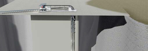
Doppelmayr, New
Possibilities for UG
Transport
Doppelmayrs Vertical RopeCon is a novel
concept which adapts the companys proven
RopeCon system to the specific requirements
of underground mining applications.
Like a conventional conveyor, this system
can be loaded by a transfer conveyor or by
an ore pass. The material is transported to
the surface on a conveyor belt. This belt is
equipped with side walls and cleats, forming
pockets for the material. Above ground,
the material is transferred to another conveyor,
another RopeCon system or discharged
onto a stockpile.
Doppelmayr said that maintenance is simple and cost effective as all moving parts are mounted on the belt and will pass the terminals at regular intervals. Access to the shaft is not required. Reuse of existing ventilation shafts is also possible. As the main drive is installed above ground, underground heat development is reduced.
Both systems provide a low-maintenance conveyance solution with minimal moving parts and high availability even in harshest operating conditions, making them a sustainable alternative to haul truck fleets.
Fenner Dunlop Rebrands
X Series
Fenner Dunlop Conveyor Belting is refreshing
its branding for the X Series line of products UsFlex, Nova-X and Ultra X
(formerly Patriot X). It said that the redesign
signifies its efforts to unify the Fenner Dunlop
brand across the Americas and EMEA
(Europe, Middle East, Africa) organizations
for a seamless customer experience.
The X Series was developed to solve the everyday challenges encountered by conveyor operators using traditional plied belting, specifically aiming to alleviate pain points such as premature belt carcass damage and wear. X Series belts are designed to be lighter and more flexible than traditional plied belting, allowing them to maneuver around critical conveyor components, like pulleys and idlers.
Fenner Dunlop has also relaunched its most heat resistant conveyor belt called OptimaHeat Xtreme. Designed in 2022, and released in 2023, this belt is made using a single ply fabric called Nova-Xtreme. This is combined with a high-performance cover compound called OptimaHeat that protects the carcass even under the most extreme high-heat conditions.
Being a single ply carcass, Nova- Xtreme isnt prone to delamination caused by impacts, trough transitions and flexing around pulleys, or heat aging to the skim compound between plies that can cause separations leading to failures. Unlike conventional heat-resistant multiply belting, the fabric also has exceptional resistance to ripping, tearing and impact.
Another advantage created by the single-ply construction is the splice strength and reliability. The use of a finger splice joint means that up to 90% of the belts tensile strength is retained, whereas a 3-ply step splice only achieves a maximum efficiency of 67%.
The OptimaHeat compound can withstand maximum continuous material temperatures up to 400°F, and extreme peak temperatures as high as 750°F. In addition to its resistance to hardening and cracking, Fenner Dunlop said the major advantages of the Optima Heat Xtreme rubber are its enhanced physical properties, including resistance to abrasive wear and superior adhesion strength.
Flender Pioneers Drive
Intelligence
Conveyor drive technology specialist,
Flender, is teaming mechanics with digitalization
to create the next generation of
mechanical drive solutions.
Andreas Evertz, CEO of the Flender
Group, told E&MJ: The digitalization of
drive technology has incredible potential.
We are convinced that drive technology
needs to be reinvented. The goal must
be to design gear units for plant manufacturers
and operators in such a way
that it is both economically and ecologically
optimal: as simple as possible and
only as large as necessary.
Julia Zundel, head of digital business at Flender, explained: The most important finding is that AIQ leads to a massive cost reduction for plant manufacturers and operators. When designing drives, the exact operating data was often not known. Today, we know that many drives could be significantly smaller in their application for regular operation and were now able to plan drive technology with almost pinpoint accuracy.
Zundel added: If mines want to achieve the perfect application-fit of drive technology and optimize their application as well as the drive train, they cant avoid digitalization. Were talking about savings of up to 50% on all relevant components. We can say that because weve been measuring and analyzing it for years.
Martin Engineering: Better
Productivity Through Clean,
Clear Belts
The introduction of modern belt cleaning
technology can help operators to
increase the volume of material entering
transfer chutes by preventing it from piling
up around the discharge zone.
This greater volume can lead to blockages in the transfer chute followed by downtime to unclog it, explained Dan Marshall, process engineer at Martin Engineering. However, designers can take a holistic approach and engineer an efficient discharge transfer point with components that work together.
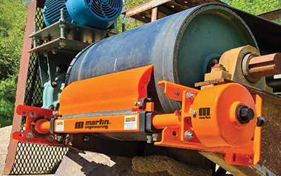
Obvious signs of discharge inefficiency are spillage, carryback, chute clogging and dust, Marshall said. Alone, each can lead to a workplace safety violation, together they result in unscheduled downtime and an increased cost of operation.
He explained that primary cleaners or scrapers can fail, causing adhered coarse aggregate and caked fines to pass by the blade and spill around the discharge area. Fugitive material can build up quickly and encapsulate the belt, fouling rolling components and causing the belt to ride on top of the course pile. Carryback is another source of fugitive dust and fines, and it can easily migrate into return rollers and take up pulleys, fouling the bearings, drives and the face of the roller.
Marshall said: If there is adequate space, install secondary and tertiary cleaners to ensure the belt is clean on the return. To improve safety, slide-in slide-out units allow a single worker to pull them away from the stringer for faster external servicing. Consider a diagonal or V-shaped plow placed underneath the loading zone right before the tail pulley that rides on the underside of the belt removing any loose traveling material. For more effective cleaning and reduced friction damage, mount a plow with torsion arms rather than one held in place by chains.
Over- or under-tensioning, and/or extending blade changes for too long can also cause spillage. Marshall said that entering a service agreement with the blade manufacturer to regularly monitor tension and change the blades could be an effective solution. Marshall recommends installing belt trackers or crown rollers along the upper and low belt path to ensure alignment, as mistracking can be another cause of spillage along the belt path and at discharge points. We recommend installing a belt tracker a distance of 3 to 4 times the width of the belt prior to the head pulley, as the trough angle flattens to ensure the belt hits the head pulley in the center, he said.
Once material is discharged down a transfer chute, obstructions may occur. Untrained and uncertified personnel should never enter a clogged chute or bin. Instead, Marshall recommends situating air cannons around the chute with nozzles pointed in the direction of the material flow. Shots of air dislodge material and prevent buildup. Uncontrolled airflow at discharge points can also create dust emissions.
By reconfiguring the chutes exit into a sloping scoop, material can be slowed and loaded onto the next belt in a controlled manner. Marshall added that retroactively installing equipment that improves both safety and efficiency should be a priority of any operator. Although the initial capital investment might be slightly higher, the return on investment (ROI) and benefits are not just fewer injuries, but reduced labor costs for maintenance, less equipment replacements, greater compliance and an overall lower cost of operation, he concluded.
Motion: How to Size
Sidewall Pockets Correctly
Selecting the correct conveyor sidewall
pocket size can significantly impact system
performance. Andrew Weisenstine,
Senior Product Manager for Motion Conveyance
Solutions, gave some useful
tips on sizing in a recent blog post.
Sidewall pocket size is the area between
the inside of the sidewalls and the
cleat, Weisenstine explained. It may
seem minor in material handling and conveyor
systems. However, sidewall pocket
size is critical for optimizing sidewall conveyor
belt performance, increasing productivity
and ensuring workplace safety.
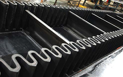
Weisenstine said: A correctly sized sidewall pocket lowers the risk of incidents and health problems by stopping material from spilling out and reducing dust generation. Also, less spillage into adjacent pockets reduces the need for environmental or facility cleanups.
The article named several factors to determine the correct pocket size for each application: The cleat pocket must be twice the size of the largest particle being conveyed. The cleat height should be 75% of the maximum particle size if the incline angle is less than 75°. If the incline angle exceeds 75°, the cleat height should be 150% (1.5 times) of the maximum particle size. The companys Durowall sidewall belting offers various cleat styles and compounds in single- and two-piece construction. Many of our larger cleats contain a double layer of fabric reinforcement for added strength, Weisenstine explained. Our rubber compound has a higher durometer than corrugated sidewall, and belt covers to maintain the cleats shape and integrity when transporting heavy material in steep-angle applications.
Durowall has proven to be a popular solution in mining applications, and the various fabrication options allow the belting to be tailored to each project. Options include cross-rigid base belting, polyurethane corrugated sidewalls and cleats. Motion offers different cleat styles and patterns to fit various applications. T-cleats are vertically oriented and are suited to conveying material up to a 35-degree incline angle. According to Weisenstine, these offer cleaner removal of material at the discharge end. C-cleats offer a greater carrying capacity than T-cleats. These are scoop-style angled cleats used for inclines over 35°. [S-cleats] form a bucket when used in a vertical application, said Weisenstine. They are vertical for the first 60% of their height, then bend at a 40° angle for the rest of the height. These are best suited where the incline exceeds 45° and in high-tonnage applications, as the vertical portion of the cleat allows it to be mechanically attached to the sidewalls, creating a more stable and durable conveying pocket.
Calculating the correct capacity of custom sidewall belts and determining the right sidewall pocket size is very important, as is optimizing the number of sidewall pockets. [There are] many benefits, such as making it easier to move materials, increasing productivity, and improving safety and environmental friendliness, said Weisenstine. Industries that understand the importance of sidewall pocket size will stay ahead of the competition while ensuring their processes are safe and sustainable.
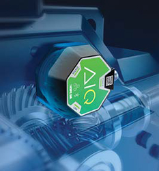
PROK, New Facility in Salt
Lake, More R&D
In January 2024, PROK opened a new
manufacturing facility in Salt Lake City, Utah. Strategically located near major
mining operations in the US, the new facility
ensures customers access to local
engineering expertise, responsive operational
and maintenance assistance, and
round-the-clock services.
The cornerstone of the new facility is its ability to manufacture PROK HDPE, a high-tech composite roller featuring visual wear-indicator technology. This directly addresses a common concern for conveyor system operators determining the condition of rollers in real-time. Providing a clear visual signal when a roller is approaching the end of its life helps prevent issues associated with worn-out rollers, reducing the risk of unexpected failures, and ensuring the continuous and safe operation of conveyor systems. Paul Byrne, managing director of PROK, said: This expansion reinforces our dedication to providing cutting- edge solutions and being close to our customers.
PROK has invested heavily in research and development, both in manufacturing automation and materials engineering, leading to the introduction of several innovative conveyor components. This includes the incorporation of advanced materials, such as nanocomposites and high-performance polymers, to enhance wear resistance and overall durability of conveyor rollers. The company recently manufactured two 48 metric tonne pulleys the largest ever produced in Australia which are now headed to a large overland conveyor in Indonesia.
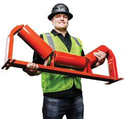
Superior: New Conveyor
Idler, Upgraded Automation
In February 2024, Superior Industries Inc.,
announced what it calls the most significant
redesign to conveyor idlers in decades.
Jason Adams, president of Superior,
explained: Tens of thousands of Superior
idlers are installed on our own conveyors
every year, so roll performance really
matters. The new idler exceeds our own
high-performance standards, and were
excited for other conveyor owners and
operators to benefit from this upgrade.
A key feature of the new idler design is an ironclad weld joint at the tube-to-end disc; the flush end disc prevents material entrapment between the roll and frame, and the weld bead is securely housed within the rolls structure, ensuring added durability. A modern, robotic welding process allows for greater weld penetration and extreme consistency.
The design of the idler bearing seals has also been revamped following a decade of rigorous testing. Superior said that the lifespan of the new standard bearing seals surpasses all other models tested, while a premium titanium seal provides extended longevity for demanding applications.
The idler redesign was supported by a $4.5 million investment in cutting-edge idler manufacturing equipment at Superiors two US idler production locations. The upgrades allow for greater manufacturing speed and an increased production rate of up to 35% for standard and custom idlers, as well as robotic manufacturing to ensure a high level of consistency.
Voith, Pulley Design
According to CEMA
and German Standards
Voith offers fluid couplings for demanding
belt conveyor drives as well as complete
drive and control solutions for mining applications.
The layout and calculations
for the companys Voith TurboBelt Hese
Pulleys are customized and consider the
corresponding environmental influences
in the application area. This guarantees
engineering optimization considering the
most common American and German
design standards, which Dr.-Ing. Adam
Gladysiewicz, manager, engineering,
material handling solutions, examined in
a recent technical article.
The book Belt Conveyors for Bulk Materials is prepared by the Conveyor Equipment Manufacturers Association (CEMA). However, in Germany, different DIN or VDI standards are used for different parts of belt conveyors, Gladysiewicz explained. In comparison, CEMA uses different definitions for carrying idlers and belts and shows large differences in the calculation of belt conveyors.
CEMA describes two types of belt pulleys: Standard pulleys with diameters of up to 1,524 mm and shaft diameters of up to 254 mm and loads of less than 490kN. These pulleys are selected from tables as finished standard products. Engineered pulleys. These should be used for belt strengths greater than 1,400 kN/m (St1400 and higher). Different definitions are given for both pulley types. Table 1 shows the pulley widths given by CEMA alongside those given in ISO 1536 and the German standard VDI 3622.
It should be noted that the CEMA standard pulleys have much smaller widths, explained Gladysiewicz. While this reduces the manufacturing costs, it also increases the risk of damage to the belt or structure if belt skew occurs. Shape and position tolerances for conveyor belt pulleys are not given in the DIN and VDI standards. In contrast, CEMA defines permissible dimensional tolerances for belt pulleys which are relatively high (see Table 2).
Pulley shafts are most commonly made of 42CrMo4 steel, said Gladysiewicz. CEMA uses the strength values for steel grade SAE 4140, which is the equivalent of 42CrMo4. However, the values are given for the soft-annealed condition. As a result, the strength of the material based on CEMA is considerably lower than that based on German standards. Consequently, Gladysiewicz recommends using the strength parameters defined in the FKM guideline Analytical Strength Assessment of Components (VDMA, 2020). CEMA also defines the minimum diameter of a shaft for a given safety factor using the equation below. In the equation, only the diameter under the shaft-to-hub connection is considered, said Gladysiewicz. In addition, the fatigue strength and plastic deformation are combined in one equation. For non-driven pulleys, this equation means that the yield strength is not considered.
The DIN 743 standards differentiate between fatigue strength and yield strength for the shaft calculations. The effects of transition radii, locking assemblies, keys, and surface finish are considered in these standards. The calculations are also much more complex; the minimum safety factor is 1.2. CEMA has approximately 32% higher safety factors on average. This can lead to smaller diameters for pulley shafts and thus reduce the cost. However, in some cases, pulley shafts designed according to CEMA can be undersized compared with DIN 743.
CEMA also defines a second condition for the selection of the shaft: deflection. Gladysiewicz explained that, in this, its assumed that the shaft-to-hub connection behaves like a joint. However, sources or references that substantiate this hypothesis are missing. Calculation of pulley bodies is also not defined or described in CEMA, he said. VDI 3622 specifies that in many cases especially at low or medium loads, the calculation of fatigue limits for the shaft and bearings is sufficient. However, the terms medium and low load are not defined more precisely. Its also stated that, in other cases, a subsequent calculation of the entire pulley shell with the shaft as a complex structural unit with finite element methods (FEM) is recommended.
Gladysiewicz summarizes that the CEMA calculations for highly loaded pulleys that are put together with locking assemblies are not suitable. The CEMA shaft calculation, which does not consider transition radii or, for tail pulleys, yield strengths, can yield shafts with insufficient fatigue strengths, he said. The general pulley tolerances, lengths, and diameters defined in CEMA can also lead to problems.
For precise pulley calculations, DIN 743 and the FKM guideline are therefore recommended. Pulleys for high loads should be analyzed as complex structural units with FEM. For the shape and position tolerances, the values proven in practice should be used. The major pulley manufacturers have their own standards that ensure correct design.