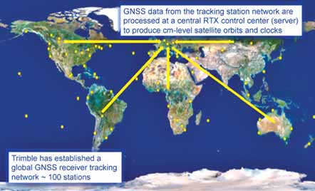
Trimble’s xFill technology can provide highly accurate interim positioning information when normal GNSS
corrections are blocked.
Exploring the Dimensions of Digital Solutions in Mine Mapping
Apart from advantages in speed of data collection and analysis provided by digital technology, perhaps its greatest benefit is this: even as mine projects become more complex, the tools needed to map them are getting easier to use
By Russell A. Carter, Managing Editor
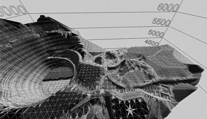
But it’s clear that the technology of sur-face mine design, planning and mapping is fast becoming a largely digital enterprise, driven by electronic and software innova-tions that are permanently changing what was once an analog, down-in-the-dirt indus-try into one that routinely adopts high-tech digital tools from other advanced sectors such as military, communications and process automation, to name just a few.
As mineral producers come under increasingly severe economic, regulatory and social pressures, their need to quickly gather, analyze and present project-critical geological and geographical data has inten-sified (See Tools to Assist in Planning and Design, p. 34) Consequently, the industry’s mapping and design toolbox has expanded over the years to include digital aerial imagery, LiDAR, digital elevation models, planimetric and topographic mapping, orthophotography, enterprise GIS and remote sensing. At the bottom of that tool-box lies one of the pioneering technologies that started the digital transition: Global Positioning System-based (GPS) navigation.
GPS is one of many disruptive technolo-gies that, upon arrival, typically alter many of the fundamental ways in which individu-als and businesses deal with everyday situ-ations. GPS, like many of its disruptive rel-atives, has been absorbed into the fabric of our lives, becoming a common personal tool for navigation and location-based social net-working as well as an essential service that lies beneath the surface of countless indus-trial activities, including many crucial appli-cations in mining. And, in the process, it’s become part of a larger family called GNSS (Global Navigation Satellite System), which is now the generic name for satellite navi-gation systems that provide autonomous geo-spatial positioning with global coverage. GNSS includes the United States’ GPS, Russia’s GLONASS, and Europe’s Galileo systems. There will be an estimated 90 GNSS satellites in orbit by 2015, and more than 120 satellites by 2020.
There’s a lot going on beneath the broad, quiet surface of GNSS, as more than 3,500 attendees at the sixth Trimble Dimensions conference learned during the annual three-day event, held in early November 2012 in Las Vegas. Dimensions is designed to showcase the latest develop-ments in Trimble Navigation Ltd.’s position-ing technology for the construction, mining, fleet operations, utility and other industrial sectors. Although the conference is tightly focused on GNSS applications, the scope of the Sunnyvale, California-based company’s offerings extends to the use of optics, lasers, unmanned aerial systems (UAS) and other technologies in mining activities that span everything from exploration surveying to haul truck dispatch.
A number of Trimble’s mining solutions have been developed in collaborative efforts involving its various subsidiaries, and business partners through a technolo-gy alliance with Caterpillar—and, of course, Trimble isn’t the only player in the game; Leica Geosystems Mining, Maptek I-Site and other well-known technology providers offer various competing or com-plementary solutions in a market sector that is evolving at quantum speed.
At this year’s conference keynote pres-entation, Trimble CEO and President Steven W. Berglund described how the scope of GNSS applications is changing, and used examples of recent business developments at Trimble to illustrate his point. Technical advances have enabled GNSS product development to shift from a task-oriented to a process-oriented focus, and with the tra-ditional focus on simple data collection from geospatial sources shifting to increas-ingly sophisticated data-analysis capabili-ties, Berglund said Trimble is moving ahead in this area to take advantage of opportuni-ties offered by improvements in:
• Sensor technology—providing a higher level of integration throughout a moni-tored system.
• Processing power—allowing higher vol-umes of data collection in real- or near real-time.
• Data storage—Massive datasets enable ‘big data’ analysis benefits.
• Connectivity—Migration to ‘the cloud’ reduces computing-capacity demands on enterprises.
• Visualization—Data-analysis presenta-tion is moving away from traditional tables and charts, toward more refined and meaningful formats.
The continued growth in volume and speed of data collection, concluded Berglund, will steadily redefine traditional methods of GNSS-based data usage in the future. But, for mine staffers who entered the industry at a point when data collec-tion, analysis and visualization for a specif-ic task often took days or even weeks to process—compared with today’s results in minutes or less—the future is already here.
Boots on the Ground
Characterizing an active surface mine as a
“constantly evolving construction site,” with
the mine model being updated as the opera-tion’s economic variables change, Michael
Maier, mining technology engineer at
SITECH Southwest / Empire Southwest
Caterpillar in Mesa, Arizona, noted in his
Dimensions presentation that one of the
more welcome aspects of higher tech in min-ing is that, even as the projects become more
complex, the tools needed to design and
measure them are becoming easier to use.
The logical product of the evolving mine site, in the era of sophisticated machine-guidance systems and high-speed data col-lection and analysis, is a mine plan that can be regarded as a living document, pre-senting changes and progress to the opera-tions and management staff in near real time, said Maier. The expanding presence of in-cab data displays showing a con-stantly updated mining plan breaks down communication barriers among work groups and essentially turns equipment operators into ‘mobile surveyors’—which, in turn, allows traditional mine surveyors to focus more on design work, consult with operators about those designs and perform quality checks on other people’s work.
Although a number of available tech-nologies have been developed to minimize the necessity of having surveyors walk the pit or scramble across rough terrain, occa-sions still arise that require conventional, on-the-ground survey techniques. The goal of Trimble, and others, is to provide tools for these tasks that are user-friendly, large-ly foolproof and sufficiently advanced to provide information that can easily be assimilated into modern data analysis and reporting software systems.

For example, last October Trimble intro-duced its next-generation ultra-light R10 receiver, featuring a new HD-GNSS process-ing engine that is claimed to provide more accurate assessment of error estimates than traditional engines. Measurements collected with Trimble HD-GNSS, according to the company, are precision-based and surveyors can collect data in challenging environ-ments where they may have been unable to collect data before. Reduced convergence times and instantaneous point measure-ments allow surveyors to start measuring sooner and up to 60% faster. Supporting 440 channels, the R10’s technology is designed to enable consistent, reliable tracking of available satellite signals for both existing and future GNSS constellations.
The new receiver also offers Trimble’s xFill technology, which employs a global net-work of Trimble GNSS reference stations to deliver position information via geostationary satellites. xFill, according to Trimble, seam-lessly fills in for RTK or VRS corrections in the event of a temporary connection failure such as a radio dead spot. As of late 2012, Trimble xFill coverage included most of Europe, Russia, the Commonwealth of Independent States (CIS), Africa, Asia and Australasia, as well as most of North America and all of South and Central America.
Trimble’s SurePoint technology con-stantly monitors pole tilt and prevents users from collecting erroneous information by only allowing data to be stored when the survey pole is plumb. Simultaneously, pole tilt angle values are stored for every point collected to ensure data traceability.
New, easier-to-use tools such as this, combined with advanced data-logging soft-ware, create opportunities for other mine work groups to perform non-critical tasks that were traditionally assigned to the sur-vey department, according to Maier. For example, personnel working on pipe instal-lation and routing at a large Southwestern U.S. copper SX-EW operation used the R10 receiver along with Trimble’s SCS900 Site Controller software to map leach pad infrastructure and piping without surveyor assistance. “Who better to locate the pipes than the pipefitters?” he asked.
This is an example of one step in a process that begins with incorporating use-ful, precision survey-based civil engineer-ing tools and techniques into the mine-design realm, and which eventually will lead to what Maier calls the ‘3-D mine’—a connected site that allows data from many sources to be universally shared to opti-mize mine performance. In the precision-surveyed 3-D mine, for example, all terrain surfaces from the pit floor to the stockpiles will be designed to flow and control runoff. Road design characteristics such as turn radius and incline will be tailored to fit the capabilities of the haulage fleet—and in this fully ‘connected’ mine, haulage equip-ment will achieve high availability because it’s running on surfaces designed for maxi-mum efficiency. The mine plan will change dynamically, taking advantage of the 3-D mine’s comprehensive data-sharing capa-bilities to ensure everyone is looking at the most up-to-date version.
This scenario is very much within the grasp of today’s mine operators, said Maier, although maximum benefit will be derived at sites that have been developed from the start with peer-to-peer 3-D capa-bilities and maximum connectivity as basic operating strategies.
An Eye in the Sky
An alternative to terrestrial surveying and
traditional aerophotogrammetry involves
the use of unmanned aerial systems
(UAS)—small, remote-controlled airframes
that can be programmed to fly in precise
patterns over medium-sized areas, collect-ing raw digital images of the terrain which
can then be processed into high-quality
orthophotos and digital terrain models
(DTMs). The key technological advances
driving the rising popularity of these sys-tems include greater miniaturization of
components, flight automation and better
integration with image-processing software.
Although UAS are not appropriate as a replacement for all applications that typi-cally would use conventional imaging or surveying methods, they can provide highly useful data in areas that may previously have been accessible only at higher cost and involving longer project-planning cycles. In suitable applications, UAS-based imagery can provide significant time sav-ings over conventional methods, along with worker and asset safety gained by eliminat-ing human involvement in the actual flight. Although extremely lightweight UAS are largely restricted to flights in good weather conditions, the slightly larger (2+ kg) air-frames typically used in mining applica-tions can fly in almost any type of weather and still provide 2–3 cm ground sample resolution accuracy, according to experts.
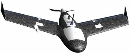
To gain a foothold in this sector, Trimble acquired UAS vendor Gatewing of Gent, Belgium, in April 2012. Gatewing’s products include the X100 UAS and Stretchout desk-top software for digital image processing and analysis. The ultra-light X100 consists of an airframe; an integrated GPS, inertial system and radio packaged as an ‘eBox’; a 10-megapixel camera; and battery. Using a tablet computer, users can define a flight plan that is automated from launch to land-ing. Terrain features are recorded during par-allel flight paths by consecutive, overlapping camera shots. A ground control station (GCS) is used to monitor the mission and allows an on-site image quality check. In addition, the GCS provides the operator with the option to intervene and abort the flight if needed. The image set consists of a number of digital images that are tagged with GPS coordinates.
The Stretchout desktop software auto-mates processing of raw images taken in flight to deliver georeferenced orthophotos and accurate DSM. As an alternative to the desktop software, users can upload images to Gatewing’s cloud solution, which auto-matically processes the images based on the users’ requirements. Within hours, users can download their orthophotos and DTMs from the cloud server.
The Gatewing UAS comes in a large suit-case-sized kit which includes the 2-kg (4.4-lb), 100-cm-wingspan airframes and its eBox, an extra body, launcher, ground con-trol station, modem, calibrated digital cam-era, lithium polymer batteries and charger, tracker tool, and spare parts and acces-sories, along with the Stretchout software.
Mark Bartlett, director of open-pit min-ing innovation at Newmont Mining Corp., told a Dimensions conference audience that he began screening several types of UAS about a year ago, looking for an answer to the question “Is this an applica-tion we can use in mining?” The Gatewing product, he explained, appeared capable of filling a niche in the company’s field and mine-site surveying activities, and offered some unique capabilities when compared with conventional methods.
In particular, Bartlett noted, Newmont was interested in using a UAS for assessing and mapping possible drill roads and pads, evaluating facility area-footprint characteris-tics, and recording prior-disturbance details on land tracts. In a recent field test, Bartlett’s crew used the Gatewing system to provide digital imagery of a rugged jungle area near one of Newmont’s African operations. Over the course of 36 flights—which required three airframe replacements due to damage from landings—the crew gained experience and insight into the benefits and drawbacks of UAS operations. These include:
• Careful attention to takeoff and landing sites—Because the UAS requires its own ground-based launcher, takeoff sites need to be reasonably unobstruct-ed; and, as landings are basically con-trolled crashes, certain kinds of ground surfaces and vegetation (short to medi-um grass, for example) are better than others (bare dirt). In addition, selecting different takeoff and landing sites may confuse the system and result in crashes.
• Awareness of atmospheric conditions and ground elevation changes—Although a UAS can fly below cloud cover that would prevent a conventional manned photogrammetry flight, because of its light weight it is very sensitive to air den-sity, which can affect takeoff and landing performance at higher elevations; and thermal currents that can affect its flight path. And, because the number of pho-tos the system will take depends on its distance from the ground, significant changes in surface elevation along the flight path can cause it to take fewer photos than expected in some cases, resulting in coverage gaps.
• Data collection and processing—UAS flights generate large files, so some fore-thought should be given to where these files will be stored and how they will be processed. Because the processing is highly graphics-intensive, Bartlett sug-gested using a powerful computer with high-end graphics capabilities—possibly, a gaming computer. And, although the standard UAS kit may include basic pro-cessing software, users may want to pur-chase more sophisticated software solu-tions to save time and extract complete value from the data.
Industry observers suggest that UAS solutions will compete more directly with ground-based laser scanning systems than with traditional aerial mapping service providers. Another presenter at the Dimensions conference, Mario Glenn Nunez, project engineer for DIP Engineering, described the results of a test comparing the application of a UAS and a conventional ter-restrial laser scanner to compile a DTM and calculate volume of a large, cone-shaped stockpile below the crusher discharge con-veyor at an open pit mine.
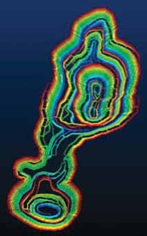
UAS setup, programming, placement of ground-control points, flight time and data processing for the cone measurement took just under two-and-a-half hours, according to Nunez, while sight-point selection and planning, scanning and data processing took five hours with the laser scanner sys-tem. Surface-image generation from the point clouds of the two systems shows a clear visual advantage with the UAS image, which provided details within the cone’s interior spaces that could not be generated with the data collected by the laser scan.
Speed and Accuracy
Even with vastly quicker turnaround times
for collecting and analyzing geospatial data
collected by the most advanced pho-togrammetry and digital surface modeling
solutions, a common issue for mine plan-ners is the amount of time typically
required to generate or update a pit plan.
For large open-pit operations this may take
weeks or more and generally requires users
that have extensive training with the soft-ware system, as well as long sequences of
mostly manual user input operations and
time-consuming editing procedures.
To reduce the time and effort needed to generate accurate, revisable mine plans, Trimble currently is in the final stages of developing a highly streamlined open-pit design package that evolved from an infor-mal conversation between some South African mine managers and engineers about a military project aimed at reducing the time required to design and construct emergency airfields in remote locations. The Joint Rapid Airfield Construction (JRAC) program was a cooperative effort in the early 2000s by the U.S. Army Corps of Engineers and their U.S. Air Force counterparts to investigate meth-ods for rapid construction and upgrade of airfields for tactical military operations.
Although much of the program’s focus was on construction and soil-stabilization techniques, one of its goals was to find ways to speed-up the design/upgrade process and develop engineering solutions that could be applied by less-than-expert personnel, often working under stressful conditions. This was the portion of the program that interested Richard Gawthorpe, principal mining engi-neer at Anglo American, and colleagues at Kumba Iron Ore, a member of the Anglo American group and operator of the huge Sishen open-pit mine in Northern Cape Province, South Africa. Looking for a similar solution for pit design and optimization tasks, Anglo American engineers joined forces with a team from Trimble about one year ago to develop a rapid pit design pro-gram that would:
• Reduce required design time by at least 80%.
• Not require extensive training or prior experience from users.
• Free-up staff with higher technical and analysis skills to perform review and optimization.
In practical terms, the engineers wanted a tool that would allow mine staff to reduce the amount of time needed to update pit design for a large mine such as the Sishen pit, which measures roughly 5 x 17 km. The upgrade process for Sishen can take as long as three months, and once completed, the plan was tedious and difficult to edit. The whole process took experienced engineers and technicians away from other more pro-ductive activities—a common problem in an industry that is chronically short-staffed and increasingly dependent on less-experienced workers.
To craft an effective software tool that could be easily grasped and applied by non-expert users, the development team focused on several key characteristics for the program: it must be a ‘simple’ solution, yet offer advanced editing capabilities; employ automated tools with controlled parameters; and require minimal training, yet provide sufficiently detailed results to allow for options analysis.
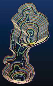
The resulting program, said Gawthorpe, called simply Trimble Open Pit Mine Design, provides a ‘paradigm shift’ in pit design, allowing dramatic reductions in time required. In on-site comparison test-ing against a conventional pit design pro-gram, Gawthorpe said Open Pit Design was able to produce a finished design in about four hours, compared with 40 hours for the conventional solution—and with 99% cor-relation between the two designs.
The development team is looking at adding several highly useful features to the existing program, said Gawthorpe. One of these would essentially reverse common design practice by using a database that contains a complete set of physical param-eters for the mine’s production equipment fleet; instead of arbitrarily assigning a stan-dard haul-road width during the design process, for example, the user could simply input the truck type and the program would automatically assign road width and turn radius based on truck size. Other future features may include enabling risk-based slope optimization, geo-risk analysis and pit development strategy analysis from detailed designs.