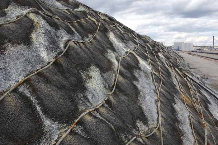
Solution piping runs along the side of a nickel heap-leach pad at the Talvivaara mine in Finland. (All photos courtesy of Talvivaara Mining Co. unless otherwise noted)
Heap Leaching: Extending Applications
A look at developments in heap-leaching technology and how mining companies are
successfully extending its application range
By Simon Walker, European Editor

According to L J Morris in his contribu- tion on solution mining to a 1984 publica- tion from the Australian Mineral Foundation, the Chinese were the first to use solution mining to produce copper. Morris cited a date of 907 AD, although noting references to the technology dated back to 177 BC.
More recent examples include the wide- spread use of precipitation in copper oper- ations in central Europe, Wales and Ireland in the seventeenth and eighteenth cen- turies, although none of the principal his- tories of mining technology from that time make mention of it. Presumably it was sec- ondary in importance to pyrometallurgy, which required a much greater level of expertise to be successful.
The production of cement copper by this means was, of course, based on natu- ral processes and as such was limited in terms of its capacity. Nonetheless, it pre- sented mine operators with an additional source of revenue merely for the cost of some scrap iron, with a production of somewhere between 300 and 500 t/y of copper reportedly having been won from copper mineralization in California as recently as the early 1950s.
Relying on natural water acidity was the stumbling block to increasing output, although there is historical evidence of acid addition being used to speed copper disso- lution as early as the 1750s at Rio Tinto in Spain. This also represented the first time ore had been deliberately formed into heaps or dumps, rather than letting natural processes take their course within in-situ rock. Where the miners there obtained suf- ficient acid to make the process viable remains a mystery; nevertheless, it appears to have worked, providing a technological foundation for subsequent usage.
Writing in the SME’s 2002 handbook on mineral processing plant design, Randolph Scheffel provided an insight into more recent applications. While heap leaching for copper was under discussion in the 1920s, he said, leaching of residual material in old stopes began in 1923 at Bisbee, Arizona, USA. This was followed by the in-situ leach- ing of ore left over from block caving at sev- eral mines, including Ray and Miami; in the late 1950s, Miami created a block-cave stope specifically for low-grade ore leaching.
Most of these were, however, precur- sors, and it was not until the uranium boom of the early 1950s that the concept of heap leaching as a separate technology gained economic credibility. The mid- 1960s introduction of new ion-exchange reagents spurred transfer of the technology back to copper, with Ranchers Exploration and Development Corp.’s Bluebird mine in Arizona being credited as the first com- mercial copper heap-leaching operation.
Having been worked since the early 1960s as a cement copper producer, Bluebird was transformed in 1968 with the construction of a new SX-EW plant. In his Solution Mining handbook, Robert Bartlett notes the system used at Bluebird was unusual by today’s practice, in that the ore was sufficiently soft to allow dozer ripping and haulage by motor scrapers, rather than having to drill-and-blast with truck haulage. Minus 6-in. (150-mm) ore was laid down on the leaching heaps in 5- to 6-m lifts, with a six-month leach cycle before a new lift was added above. The top 1 ft (300 mm) of each lift was decompact- ed by ripping before leaching began.
The next stage in heap-leaching devel- opment, using the concept for gold recov- ery, was swift to follow. The Cortez and Bootstrap operations in Nevada are now credited with being the first out of the blocks in this respect, in 1973 and 1974 respectively, leading the way in what is now one of the industry’s standard methods of gold recovery. However, it is also important to remember that just 30 years ago, gold heap leaching was very much still at an early development stage: the 1985 edition of the SME’s mineral processing handbook barely mentions it, with little more cover- age given to heap-leaching copper either.
Today, heap leaching is not only used worldwide for copper and gold, but research has shown that other metals can also be recovered economically from low- grade resources by tuning the technology appropriately. The focus is once again on uranium, while the nickel boom of a few years ago provided the impetus for tech- nology transfer there. And, it has also been proved that successful heap leaching is not just achievable in temperate climates, with operations now in progress from the Arctic to the Equator.
From the Bottom Up
While first-generation leaching heaps were
often built directly onto relatively imperme-
able subsoil, practice soon evolved to incor-
porate geomembrane liners between the
pad and its foundation. Initially envisaged
as being a means of minimizing losses of
pregnant liquor to the underlying ground,
and hence for project economics, the sys-
tem soon became mandatory for environ-
mental reasons. Remember Summitville.

While it is obvious the liner itself should be protected from whatever is dumped on top of it, especially if the pad is to be used on a regular load-unload basis, current sys- tems go a stage further. And there is more to liner selection than might at first be apparent, with Breitenbach listing factors such as the liner material, thickness and surface roughness as being critical, as well as the loading characteristics of the first and later heap lifts, and the quality of the installation process.
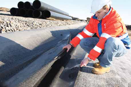
The use of composite liners can also be advantageous in some circumstances, with the gemembrane underlain by a bentonite- based geosynthetic clay liner. The U.S.- based supplier, Colloid Environmental Technology Co. (CETCO), claims its ben- tomat GCL system can offer a number of benefits: the material has a lower hydraulic conductivity than normal soils or compact- ed clay; it protects the geomembrane from puncture damage from beneath; and it cushions the geomembrane from point loading from above.
CETCO recently supplied a composite liner system to the new Talvivaara nickel mine in Finland, where the local climate places additional demands on liner integri- ty. In addition to being easier to install than compacted clay, since it is supplied in rolls of internally reinforced bentonite, the GCL is better able to withstand differential set- tlement and shear loads, the company said, so offers long-term protection to the all- important geomembrane that guides the pregnant leachate to the collection ponds.
With multi-lift heaps now mainstream technology, operators can be faced with the choice between relying on the original liner to maintain integrity throughout the entire life of the project, or to install inter-lift lin- ers. These, according to Mark Smith (then at Vector Engineering), can have signifi- cant benefits as well, since the leachate from upper lifts does not have to travel right down to the base of the heap and so can be collected more quickly. At just 0.5 mm, inter-lift liners are typically much thinner than their base-level counterparts, and require the surface of the previous lift to be prepared carefully before installation.
Points for consideration here include the provision of adequate drainage pipes at each level, and the risks involved in creat- ing zones of lower shear strength at regular intervals up the heap.
Also of significance, especially as heap heights are increasing, is the loading effect on the flexible pipework used both to col- lect pregnant leachate and to supply air within the heap itself. A recent paper by Mark Smith (now with RRD International Corp.) and K.P. Sinha of Ausenco Vector looked at the issue.
In it, they pointed out it is very difficult to replicate in a test rig real-life field condi- tions inside a heap, since factors such as the way that overliner material is em- placed, whether heavy equipment is used for loading the heap, and the natural soil conditions beneath the heap can not be modeled effectively. Neither can the influ- ence of pipes lying in close proximity to one another, nor the response to loading of pipe joints, which behave differently to long straight runs. What is acceptable in terms of pipe buckling and deflection within a heap- leach operation may be much greater than would be the case in a typical civil engi- neering installation, with different require- ments on pipe materials and connections.
To Flow or Not to Flow?
The way in which leaching fluids flow
through a heap has come under increasing
scrutiny in recent years, with clear proof
that the heap consistency can have major
implications for a leaching project’s speed
and yield. In a paper presented at the
Tailings and Mine Waste Conference in
2008, Jim Kunkel from consultants Knight
Piésold set out to debunk some myths
about how leaching solutions actually flow.
The first of these, he said, is that leach- ing solutions travel as a wave front down through the heap at an even velocity, whereas the reality is that fingering is the norm, with the solution penetrating some parts of the heap faster than others. Indeed, depending on the internal struc- ture of the heap, and the particle size dis- tribution, it may be difficult to reach some of the ore with solution effectively.
Another myth addressed concerned the presence of fines within the heap. It has long been held, Kunkel said, that fines block up pores in the ore fragments and generally impede the flow of solution through the heap.
Not so, he said. “Fines are necessary to ‘spread’ the applied lixiviate and provide wetting to the ore away from drippers. Even if flooding or spraying is used for lixiviate application, preferential flow can more easily develop without fines.” The result of there being no or low fines, he added, is unwetted and unleached ore.
Citing an example where testwork had been carried out on ores containing 1.4% and 4.1% fines, this showed 7% and 2% of the ore, respectively, was unleached, while in the first case no less than 86% of the ore was poorly leached, he said. With the in- creased level of fines in the mix, this propor- tion fell to 50%. However, where segregation occurs, perhaps because of the method of heap construction, the situation can arise where there are effectively two leaching processes in operation simultaneously, one in the fine material and one in the coarse.
Air flows through the heap are also crit- ical to successful leaching, and if the level of water saturation in the heap is too high, it will effectively block the air flow, and hence the supply of oxygen to the leaching process.
The New Generation
While most of the industry’s experience in
heap leaching over the past 50 years has
come from copper, gold and silver recovery,
the technology is now being applied more
extensively, in particular to uranium and
nickel.

Advantages, he went on, include the low capex and operating costs involved, and the elimination of grinding and solid/liquid separation. In addition, run-of- mine ore need not be crushed, and no tail- ings dam is needed.
On the other hand, leaching times are much longer than for conventional sys- tems, with lower recoveries, and at the end of the project, environmental closure costs may be high, especially if sulphide miner- alization is present. Above all, he said, the pre-production testwork must be undertaken thoroughly, with adequate safety factors applied during scale-up.
Current projects focusing on acid-based heap-leaching include those at Ranger in Australia, Rössing in Namibia and Somaïr in Niger, while the first commercial use of alkaline leaching is now ramping up at Areva’s Trekkopje mine in Namibia.
Based on measured and indicated resources of 334 million t grading 0.13% U in carnotite mineralization, Trekkopje has been engineered in three stages to heap- leach 100,000 t/d of ore for an output of around 3,200 t/y of uranium over a 12-year life. A leach pad measuring 600 m wide by 2 km long is being used in an on-off sys- tem, with spent ore being returned to worked-out areas of the mine for disposal.
Run-of mine ore is crushed, screened and agglomerated before being stacked on one of the 30 cells within the leach pad, of which about 22 will be active at any time. Sandvik has supplied six CH880 cone crushers to the project, while engineering and procurement has been undertaken by South Africa’s Bateman Engineering.
Heap-leaching for nickel has also fol- lowed different development routes, with separate technologies being used in the treatment of sulphide and laterite ores. One of the early leaders in laterite process- ing, European Nickel, put its Çaldag proj- ect in Turkey on care-and-maintenance at the end of last year following permitting delays and is instead focusing on Acoje in the Philippines. The company acquired Acoje following its merger with Rusina Mining, which had already begun a leach- ing trial on the mixed limonite-saprolite ore at the end of 2009.
European Nickel is now proceeding with a full feasibility study on Acoje, which has a base-case output of 24,500 t/y of nickel over an initial ten-year life. Meanwhile Çaldag, where it began its pilot- scale testwork in 2005, has proved that acid leaching can produce a high-grade mixed nickel-cobalt hydroxide concentrate, at lower capex and operating costs than conventional recovery technologies. So said Mark Hanlon, the company’s finance director, in a presentation to the Paydirt 2010 Australian Nickel Conference in Perth last October.
Meanwhile in Finland, the latest reports from Talvivaara Mining show that the com- pany expected to produce between 11,000 and 13,000 t of nickel in 2010, as its open-pit, heap-leach operation ramps up toward its 50,000 t/y target by 2012. Talvivaara uses bioleaching to generate acid naturally within the heap, with air blown in through a pipe network at the heap base.
At full capacity, the operation will treat 22 million t/y of ore, with crushing fol- lowed by agglomeration using sulphuric acid before stacking on the heap. After bioleaching for 18 months, the partly spent ore will be reclaimed and restacked on a secondary heap, where residual leach- ing will continue. As well as nickel, the operation recovers zinc, copper and cobalt, with the company having recently announced its intention to recover the small amounts of uranium also present in the ore, which reports to the leachate.
Big Opportunities
No question, there have been some major
advances in our understanding of the
mechanisms involved in successful heap
leaching over the past 50 years. Little won-
der, then, its application continues to diversify, both geographically and in terms of the
commodities to which it can be applied.

Taking a somewhat different approach, Ore-Max cites the problems that can occur when drip emitters designed to operate with clean water become increasingly clogged with recycled, and hence dirty, leaching solutions. Better internal filtration in its Max-Emitter system helps to reduce this effect, the company states, noting that experience on both copper and gold heaps has shown recovery improvements.
However, it is also important to realize that heap leaching is not just a cheap and simple way of getting metal out of rock. Each project must be evaluated thorough- ly, with testwork that is appropriate to the site conditions. Projects that have failed to reach expectations, or where there have been other glitches, have given the con- cept a generally undeserved reputation for unreliability. In reality, however, many companies today rely on successful heap leaches for a significant, reliable contribu- tion to corporate income. The technology continues to develop and is becoming increasing sophisticated. A mainstay that is here to stay.
References:
Scheffel, Randolph E. Copper heap leach
design and practice. In: Mular, Andrew L,
Halbe, Doug N and Barratt, Derek J (eds),
Mineral processing plant design, practice,
and control: proc., vol 2, SME (2002).
Bartlett, Robert W. Solution mining: leach-
ing and fluid recovery of materials.
Routledge (1998).
Breitenbach, Allan J. Heap leach pad
design and construction practices in the
21st Century. Vector Colorado LLC.
Kunkel, Jim. Heap leach lixiviant flow:
myth versus reality. Presented at: Tailings
and Mine Waste ‘08. Knight Piésold
(2008).
Morris, L J. Solution Mining. In: 8th
Australian Groundwater School, Aus-
tralian Mineral Foundation (1984).
Sinha, K P and Smith, M E. A holistic
assessment of pipe design in heap leach
operation. RRD International Corp. (2010).
Smith, Mark E. Inter-lift liners in copper
heap leaching. Vector Engineering (1996).
Taylor, Alan. Copper heap leach design—
hit or miss? Alta Metallurgical Services.
Taylor, Alan. Uranium heap leaching gain-
ing popularity. Alta Metallurgical Services
(2009).
|
Measuring Success By its very nature, heap leaching should be simple. However, as operators worldwide have discovered to their cost, in practice there can be a big difference between the concept and achieving the expected return in terms of output. A whole raft of factors can come into play, not least of which are the permeability of heap itself, the mineralogy of the ore being leached, and the way in which the heap and its infrastructure have been built. A problem commonly experienced is while metallurgical test- work has shown that viable recoveries of the target metal can be made over a certain time-span, scaling up the system to operational size shows that this is not, in fact, the case. Typical challenges cen- ter on metal dissolution being slower in practice than in the lab’s pilot rig, leading to revenue streams that do not fulfill the project’s economic model. It is often the case that the metal will be recov- ered over time, but not at the predicted rate. In a paper presented in 2002, Alan Taylor, principal of Australia- based Alta Metallurgical Services, noted that while heap leaching has become increasingly popular for the recovery of copper from oxide or secondary sulphide ores, “it is not without its pitfalls, and a number of projects have suffered from slow ramp-up times and [have] not lived up to expectations.” This, he went on, “highlights the need for improvements in testwork, scale-up and system design procedures. Although progress has been made, procedures are still in a state of flux, with no universally recognized standards.” Taylor provided some guidelines, drawn from his own consult- ing experience, for the testwork that needs to be done before the decision can be taken to construct a heap-leach operation. One of his key pieces of advice may appear overly simplistic, but is clear- ly based on pitfalls he encountered with client companies. “Being systematic is the name of the game,” he said. “Avoid taking appar- ent short-cuts; you will usually live to regret it.” One example cited is that of carrying out column leach tests which, not surprisingly, can prove to be time-consuming. “Final column tests must be at the full projected lift height. This can lead to long test duration, especially for sulphides. For example, a 6-m-high sulphide column test can take close to a year to com- plete,” Taylor said. |